It's getting to where fewer and fewer
designers
are
making flat drawings. The trend is to design,
test
and machine in 3D, even for parts that have
traditionaly
been flat 2D. Plates, brackets and other
simple parts
are being drawn in solid modeling packages
like
SolidWorks & Mechanical Desktop.
Mastercam also
has Solid Modeling capability and is
compatible
with
the packages listed above.
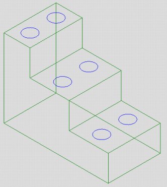
People are drawing with solids for many reasons
The
parts shown below has drilled holes on several levels.
With most Cam systems these would have to
be machined
as separate toolpaths. Because all of the
depths are different.
Lets assume all of the holes are supposed
to be tapped to
a depth of .950. The
absolute
depths, from the top of
the part would be different for each level
of holes.
Here's how Mastercam can make that easy to do.
 _
_ _
_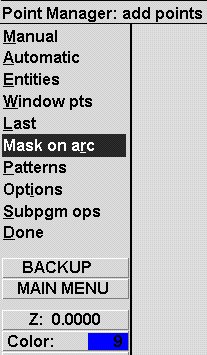
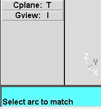
At the bottome of the screen you'll see a
prompt
to "Select arc to match". What we're
going to do
is pick the arcs by their size, which in turn
selects
their locations in X Y & Z.
 Pick any one of the arcs.
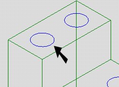
A prompt at the bottom will say..
"Enter the arc radius matching tolerance"
and show a value of
.001.
Press Enter.
It should be asking "Tolerance for
selecting
similar holes".
This means, any hole like the one you selected,
within .001 of the same size, will be
part of the group
being drilled.
Next it wants to know where to look for
similar
holes.
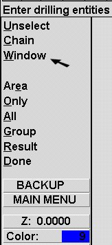 Select
"Window" .....
Select
"Window" .....
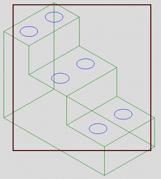
....and put a window around the entire part
(or at least all the holes).
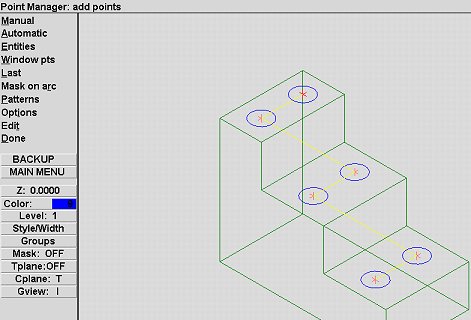
Now the Point Manager is displayed.
This is where you deceide if you like the
order
the holes will be drilled. if it looks like
the
picture below, you can just press
"Done".
If not,
you want to select "Options"
to sort the points
into the order you want. Be sure it
starts from the
highest point (top) of the part.
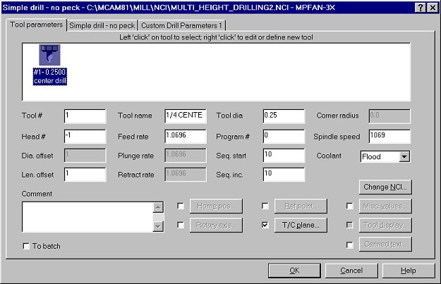
On the Tool parameter page, pick a center
drill.
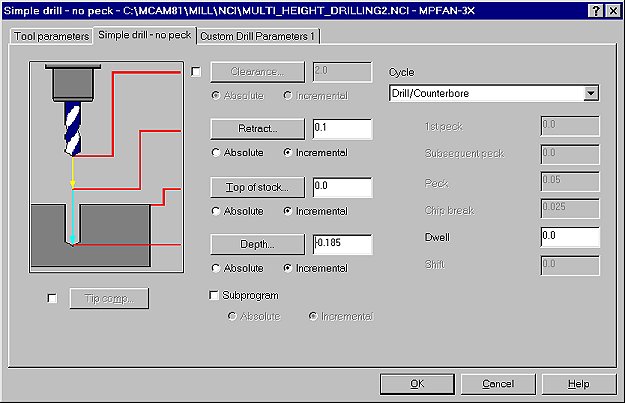
On the Simple drill (drilling parameter)
page
set the
values as shown below and set them to
Incremental.
This is the important part:
The depth will be Z-.185
From The XYZ Center Of The Hole.
I dont have to assign a different
depth
for each level.
The system knows where the circle is and it
calculates the
depth from that "point". Press
OK when your finished.
To do the Drilling & Tapping, we could
go back and repeat
the selection process, pick our tools and
set the information
for each operation. Or we can
copy the operation we just
created, make copies and modify the
copy.
A much simpler
process. And I like simple.
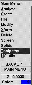
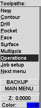
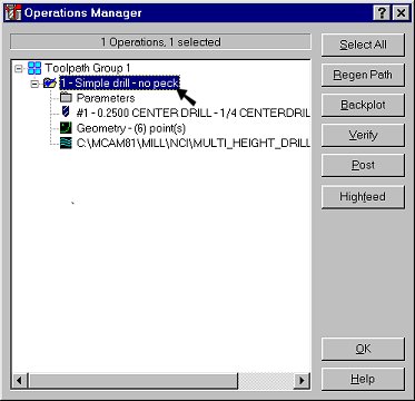
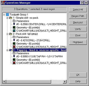
Back on the Toolpath menu. Select
Operations.
In the operations manager point your cursor
on the
operation (the blue bar), hold down your right
mouse
button and slide your mouse down a little
bit.
Let go of the button.
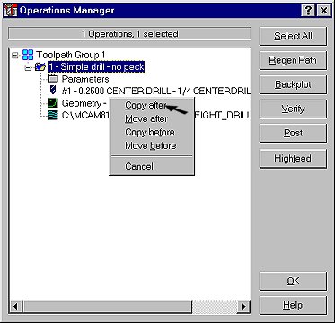
Select Copy After and you'll have a
duplicate
operation.
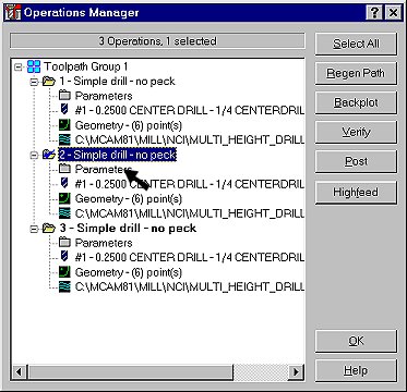
Do this again until you have 3 operations.
After you have 3 operations, select the
parameters
of the second operation. Get a
27/64 drill.
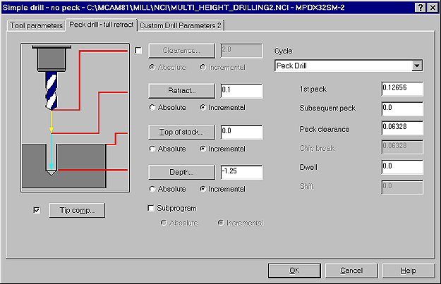
Change the values of the depth to -1.25 as
shown below.
Be sure the Cycle is Peck drilling. Press
OK when finisned.
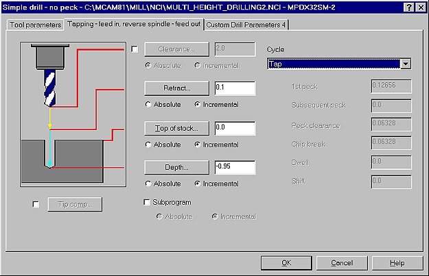
Select the Parameters for the 3rd
operation.
Get a 1/2-13 Tap.
Change the values of the depth to -.950 as
shown below and be
sure the Cycle is for Tapping.
You'll see small red X's
in the modified operations.
Press Select
All and then Regen Path.
Your done.
Post the file and all of the depths will
be set to the point
position.
See the posted code for several different control types