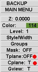
shown at the lower part of the left menu.
They can also be selected by their hot keys.
Alt 5 is the hot key for Cplane.
Alt 4 is the hot key for Tplane.
The Basics
Cplane allows you to set
a flat plane, where geometry
can be created. Standard
Cplane's are Top, Front, Side etc....
Tplane allows you to set
a flat plane, where machining
can be performed. With Tplane
you can machine on all
sides of the part.
Cplane / Tplane &
Alt o (letter o, not number zero) are
used to set the Origin (zero
point) for construction
and machining. This means
you can float the XYZ
zero location to any point
on your part
Cplane & Tplane are accessed
by clicking on the button
shown at the lower part
of the left menu.
They can also be selected
by their hot keys.
Alt 5 is the hot key
for Cplane.
Alt 4 is the hot key
for Tplane.
The Setup Procedure
The first thing to do is
set the Cplane & Tplane, for each
side that needs to be machined.
After these are set, they
can be named and recalled
as needed. Cplane & Tplane
can be accessed with selection
at the lower left of the
Main Menu, or by using
the Alt "hot keys".
Save & unzip the
sample part to your Mastercam
drawing folder and open
it.
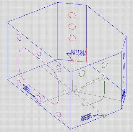
Setting Up The Front
Zoom in (F1) to get a better
liew of the front of the part.
Cplane (Alt 5) - Front
Cplane (Alt 5) - Alt o
(the letter), pick Center and select the
small light blue circle
indicated on the front of the part.
Tplane (Alt 4) - Next
menu - =Cplane
This makes the Tplane the
same as the Cplane and it's origin.
Saving & Naming The
Settings
Cplane (Alt 5) - Next menu
- Save named
type in the name FRONT OF
PART,
check the Associative box,
set the Work Offset to 0
(-1 means no work offset).
Click OK
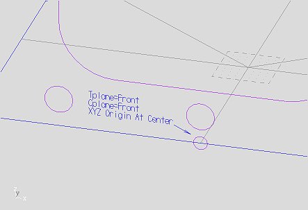
Setting Up The Side
Cplane (Alt 5) - Side
Cplane (Alt 5) - Alt o
(the letter), pick Center and select the
small dark green circle
indicated on the side of the part.
Tplane (Alt 4) - Next
menu - =Cplane
This makes the Tplane =
to the Cplane and it's origin.
Cplane (Alt 5) - Next menu
- Save named
type in the name RIGHT SIDE
OF PART,
check the Associative box,
set the Work Offset to 1.
Click OK
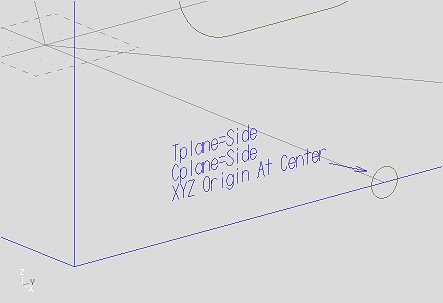
Setting Up The Right Back
Angled Side
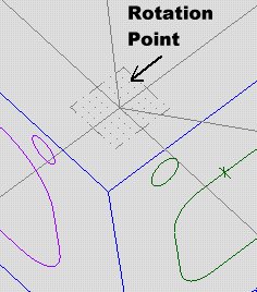
Rotate the part so you can
see the dark blue geometry clearly.
I suggest doing a right
click of the mouse, selecting Dynamic
and picking the part center
as the rotation point.
Cplane (Alt 5) - Entity -
pick the two dark blue lines, selecting
the lower line first and
the vertical line second (the first
represents the X axis and
the second line represents the Y axis).
The screen will show a tetrahedron
(XYZ axis thing).
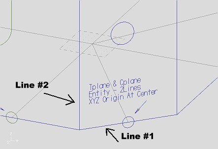
The Z axis should be pointing
outside the part.
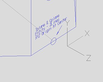
If it dosen't look like
the axis shown below,
select Next. If is
does look like this, select Save.
Cplane (Alt 5) - Alt o
(the letter), pick Center and select the
small dark blue circle indicated
on that side of the part.
Tplane (Alt 4) - Next
menu - =Cplane
This makes the Tplane =
to the Cplane and it's origin.
Cplane (Alt 5) - Next menu
- Save named
type in the name BACK RIGHT
SIDE OF PART,
check the Associative box,
set the Work Offset to 2.
Click OK
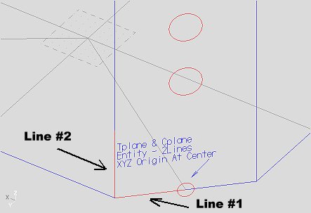
Setting Up The Left Back
Angled Side
Rotate the part so you can
see the red geometry clearly.
Cplane (Alt 5) - Entity
- pick the two red lines, selecting
the lower line first and
the vertical line second (the first
represents the X axis and
the second line represents the Y axis).
The screen will show a tetrahedron
(XYZ axis thing). The Z axis
should be pointing outside
the part. Select Save.
Cplane (Alt 5) - Alt o
(the letter), pick Center and select the
small red circle indicated
on the that side of the part.
Tplane (Alt 4) - Next
menu - =Cplane
This makes the Tplane =
to the Cplane and it's origin.
Cplane (Alt 5) - Next menu
- Save named
type in the name BACK LEFT
SIDE OF PART,
check the Associative box,
set the Work Offset to 3.
Click OK
Select A Plane For Machining
To select a plane for geometry
creation or toolpath, select
Cplane (Alt 5) - Next menu
- Get named .....
and a list of all the available
(defined) planes will be shown.
Select the plane to be machined.
Create toolpaths as usual
for that plane.
Mastercam will treat that
plane the same
as if you were machining
the top of the part.
Repeat as necessary for each
side.
Horizontal Postprocessor
Most of the horizontal postprocessors
I've written conform
to the standard of the Front
being B0(zero). Below is a post
that I use for customizing
other horizontal machines. It's what
I call my "base" post. If
you have a Fanuc type control this post
should work for you. There
are a number of internal "switches"
that can be turned on or
off.
Here is the link to download the MPFan-BX postprocessor.
For more information on editing or modifing posts check out this link.
For more information on my
screen colors check out this link.